
Everything Engineers, Contractors, and Owners Need to Know to Create the Optimal Indoor Pool Environment.
CHAPTER EIGHT
Specific market segments have gravitated towards unit designs because of their overall features, ease of installation, first cost, and system performance.
HOTEL AND RESIDENTIAL MARKET
Hotel and residential pools are typically smaller with light usage compared to institutional pools. Besides the pool water heating option, they tend to select unit designs without some of the other heat recovery options that are usually incorporated into larger units:
- This configuration is usually refrigeration based with the outdoor ventilation air connected directly to a special intake at the unit.
- The space heating coil is also mounted internally.
- The exhaust fan is usually installed in the space with its intake over the hot tub.
- The air conditioning heat rejection is to a remote outdoor air-cooled condenser.
The configuration in Figure 12 is very popular in hotel and residential applications because of their compact footprint and limited service access requirements.
There are a multitude of other configurations available should a horizontal unit or outdoor packaged system better suit the project. The heat rejection can also connected to a geothermal loop, dry cooler, or cooling tower.
FIGURE 12: SLB CABINET
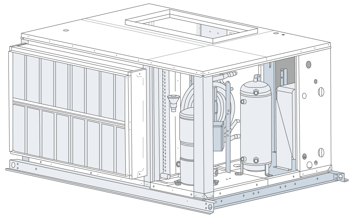
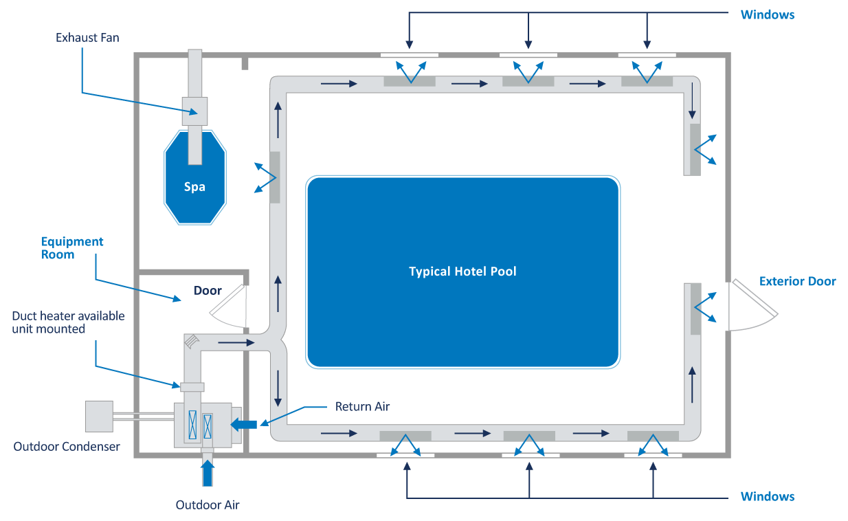
FIGURE 13: TYPICAL HOTEL AND THERAPY POOL LAYOUT
PURGE-ECONOMIZER LAYOUT
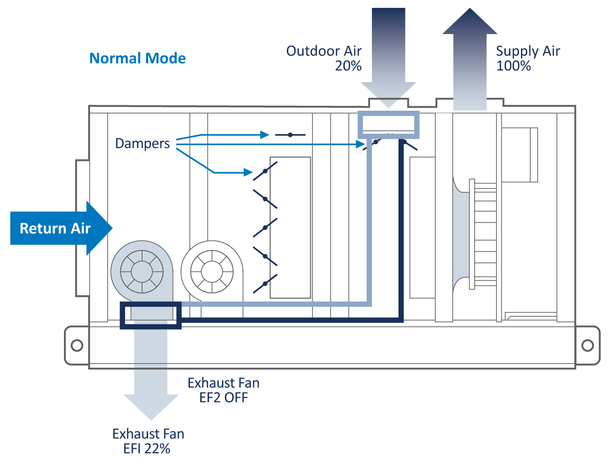
This configuration is popular in larger systems that are looking for flexibility with outdoor air amounts. These systems are designed with multiple dedicated duty exhaust fans. The first exhaust fan (EF1) is sized to maintain the room’s negative pressure by exhausting 10% more room air than is introduced to the space as code-mandated ventilation outdoor air. The second exhaust fan (EF2) is sized to allow up to full purge/evacuation of the space with a 100% outdoor air mode.
Figure 14 displays a unit in “Normal Operation” where EF1 maintains the room’s negative pressure. EF1 can be unit mounted or remotely installed with its intake located above the whirlpool whenever appropriate.
EF2 is normally off and operates only when a purge or economizer demand exists.
FIGURE 14: NORMAL MODE

The outdoor air intake is set to introduce the code-required ventilation outdoor air (aka minimum OA) until the system goes into Purge-Economizer mode when it opens to 100%.
These minimum outdoor air and EF1 air streams at vastly different conditions present a perfect opportunity for heat recovery. The heat recovery coils could easily be introduced into the air streams of this unit configuration. This approach to heat recovery offers the best performance and design flexibility while staying in the smallest possible cabinet. Figure 15 displays a unit in “Normal Operation” with the glycol heat recovery coils in place.
FIGURE 15: NORMAL MODE WITH GLYCOL HEAT RECOVERY
If the system design has remote exhaust fans, the glycol runaround loop can still be used for heat recovery.
A significant added benefit to heat recovery is the tempering of the outdoor air before it can mix with the system air. Tempered outdoor air will not create condensation problems during the cold weather. In cold climates, it is very common to add a separate heating coil for the outdoor air if heat recovery is not being utilized.
Figure 16 displays a unit in “Purge-Economizer mode.” There are four significant benefits to this configuration:
FIGURE 16: PURGE-ECONOMIZER MODE
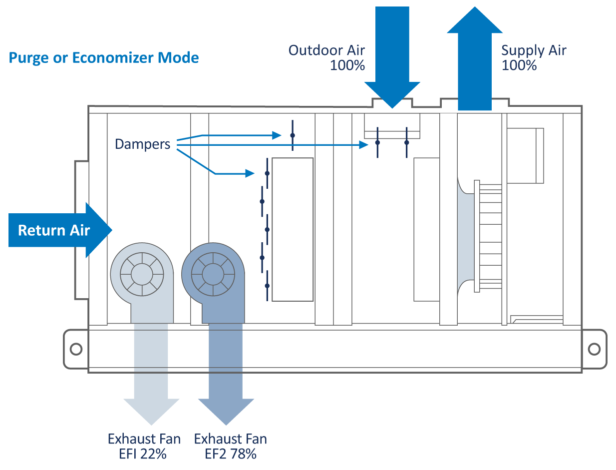
1. 100% air purge capability available at any time. The operator can super-chlorinate the space with 100% outdoor air to quickly clear out any airborne chemicals.
2. It also allows for a means to deliver a complete air change of the space should it require a quick purge.
3. Built-in economizer operation. All controls and mechanical equipment are already in place to operate in economizer cooling and dehumidification modes whenever the outdoor air conditions are suitable. This offers the operator the most economical year-round system operation.
4. This configuration consumes significantly less energy than traditional supply/return fan economizer systems with a mixing box because of the specific duty exhaust fans. They only operate when required compared to the supply and return fan configuration that has both full-sized fans operating year round. EF1 is a very small horsepower fan. EF2 operates only when called upon or when the outdoor conditions are suitable for economizer operation whereas the traditional approach has two full-sized fans operating year round.
These system features can be designed into the ductwork or incorporated into the unit as a complete package.
TABLE 6 – EXHAUST FAN OPERATION
| EXHAUST FAN OPERATING SEQUENCE EXAMPLE | |||
|---|---|---|---|
| Exhaust Fan EF1 | Exhaust Fan EF2 | Outdoor Air | |
| Normal Operation | ON | OFF | Minimum required by code |
| Purge–Economizer Mode | ON | ON | 100% |
EVACUATOR INTEGRATION
From an HVAC standpoint, the Evacuator is an exhaust fan that just factors into the total exhaust air required for the space. They generally exhaust the same amount of air needed to keep the space negative, so they blend into the design nicely.
There are several ways to set things up with Evacuators:
- Evacuators are totally stand alone.
– Simply reduce the CFM of EF1 in the unit accordingly.
- Provide a dedicated air path, the EF1, and use the dehumidifier’s exhaust fan.
- Provide the dedicated air path, EF1, and a heat recovery coil.
- Provide a heat recovery coil in the dehumidifier for outside air preheat, and a remote heat recovery coil gets installed at the Evacuator exhaust air.
The Evacuator control strategy is either constant air volume (CAV) or variable based on a VOC meter. The dehumidifier should be set up to modulate outside air in concert with the Evacuator exhaust.